One of the instruments that we see fairly regularly in our shop is the Leblanc paperclip contrabass clarinet. Being very specialized and featuring an extremely unique timbre, it is typically a very sought after and valuable instrument. However, there has been a slight disconnect in the market for these instruments in that they come in two different versions: one that plays down to D which is the more common of the two, and more preferable to some for the way it plays, and one that goes down to C which has more practical application because of the expanded range. The primary issue here is that because of these differences, the low C is not only a much more rare instrument, but it is also the more valuable of the two, typically going for upwards of $2000 more. Seeing this, Matt Stoecker – my boss, and the owner of The Mighty Quinn - saw an opportunity to close the gap, and approached me sometime around the end of 2018 to design an extension system that could fit onto any Leblanc low D paperclip contrabass, to essentially convert the instrument into a low C; the idea being that people who already have a low D could spend a comparatively small amount to convert their existing instrument rather than buy something entirely separate, should they need to upgrade.
Although this would be a huge undertaking – working alone, with only my lathe, some files, a torch, and my trusty jewelers saw to guide me – the concept was not terribly outlandish; after all, with the factory low C extension tube removed, the two instruments are absolutely identical with the exception of a few posts brazed onto the lower joint of the low C to allow for the additional keys. As tricky and involved as it would be, the more I thought about it, the more invested I became. As a repair tech who has seen these instruments countless times before, I've come to respect the Leblanc paperclip contrabass as a complex instrument with a number of effective solutions to some tricky design problems, but also one that has some glaring quirks. By and large, these elements amount to nothing more than some additional considerations when repairing the instrument, but there are some that present legitimate problems for the longevity and stability of the instrument. In the grand scheme of things, this project would only encompass a small portion of the instrument itself, but getting the chance to iterate and potentially improve on the original design to help alleviate some of these quirks was an intriguing prospect; one that I welcomed with enthusiasm.
Design Process & Manufacturing
The first step in the design process was to start with the four elements of the tube that I knew had to be present in the extension system.
At the top of the instrument between the body and the bell would be the tube itself. Because length, diameter, and tone hole placement are non-negotiable factors due to their effects on tuning, this would remain more or less the same as the standard tube on a macro scale.
The key system would be split into two components: the upper half which interacts with the extension tube keys, and the lower half which contains the touch pieces, placed just above the right hand thumb rest.
The two key clusters would interact with each other via a series of linkages which cross the “center” of the paperclip design.
No component of this could be a permanent modification to the instrument
Being that the measurements for the tube itself could be more or less copied from the existing design, I estimated that it would be the simplest component to make, so that is where I started. The first step in this process was picking materials and since I had never attempted to make something like this before, it was something that was an early source of anxiety for me - after all, I only had a cheap mini lathe to work with (which broke on two separate occasions during this process and had to be replaced with a much more capable machine) so if I couldn't find a source capable of supplying a close enough approximation for the body tube, the entire project would have to be put on hold indefinitely. Luckily, I was able to find a near exact match for the brass tubing that composed the factory made contrabass clarinets, so work could begin.
Back in my shop, I cut the tube to the proper length, marked where the two tone holes would be placed, and bored out two identical lengths of tubing for what would be the tone holes themselves. This was the beginning of my next hurdle: without a pipe notcher, I would have to find a way to accurately cut the profile of the tone holes so that they perfectly fit the curve of the body tube; otherwise, if there was any gap between the body tube and the bottom of the tone hole, it would be nearly impossible to get a clean brazing line. In order to do this, I measured the depth of the factory tone holes on the most shallow end to get the minimum depth of the tone hole, and glued a paper stencil to the uncut brass tube; the purpose of the stencil being to accurately mark the curve that would need to be cut so that the two tubes could intersect at a 90 degree angle. I then secured the tone hole tube in my vice, and carefully cut along the lines of the stencil with my jewelers saw to get the proper curvature, cleaning it up with a file as needed to smooth the line and eliminate any high spots. With the profile cut on both tone holes, I laid them on the marked areas of the body tube, brazed them in place, and drilled holes in the center of each on the body tube, clearing off the remaining brass using my Dremel tool until I achieved a perfectly flush joint on each tone hole.
Testing the fit of the post strip, and the key cups
The pad cups, made out of solid brass bar stock
Next came the receiver which was fairly simple, being just a slightly larger brass pipe turned down so that it was the right thickness, then soft soldered onto the extension tube. Key posts were also fairly simple, and were something that I had made plenty of times before; what can be said, however, is that having to do so many of them for a single project gave me a chance to solidify my process, and come up with the most streamlined approach given what my shop would currently allow. My process evolved slightly over the course of working on this project but at the simplest, single post design, I eventually settled on a three step system. To start, I put a brass bar on my lathe and turned it to apply a slight angle to the post, then I drilled out the center with a 1/16th bit and parted it at the start of the angle. Next, I put a brass ball bearing on the chuck, flattened one end, and partially drilled it out with the same 1/16th bit. Finally, I inserted a 1/16th brass rod through the post, put the ball bearing on top, and brazed everything together. The purpose of the brass rod is two-fold; first, it ensures that the post and the ball bearing are perfectly aligned and secure for brazing and second, leaving a small 1/16th amount sticking out at the base of the post allows the post to be plugged into a pilot hole drilled on whatever surface it will be mounted, keeping the post accurately aligned during final brazing.
The assembled post, in a double configuration. Here, you can see the different components as they are all assembled; the angled rod, two ball bearings, and the rod connecting them.
The initial design for the posts involved turning the end of the ball bearing down only partially, so it could directly plug into the post. This was not only not as stable during the brazing process as the later rod design since the plug had less depth, but it involved more much more finicky measuring and more tool changes; having to turn down the ball bearing the perfect amount each time, and necessitating more switches between my cutting bit and drill bit. Why not just use a drill bit to get the exact pilot hole on both the post and the ball bearing without any extra measuring or tool changes?
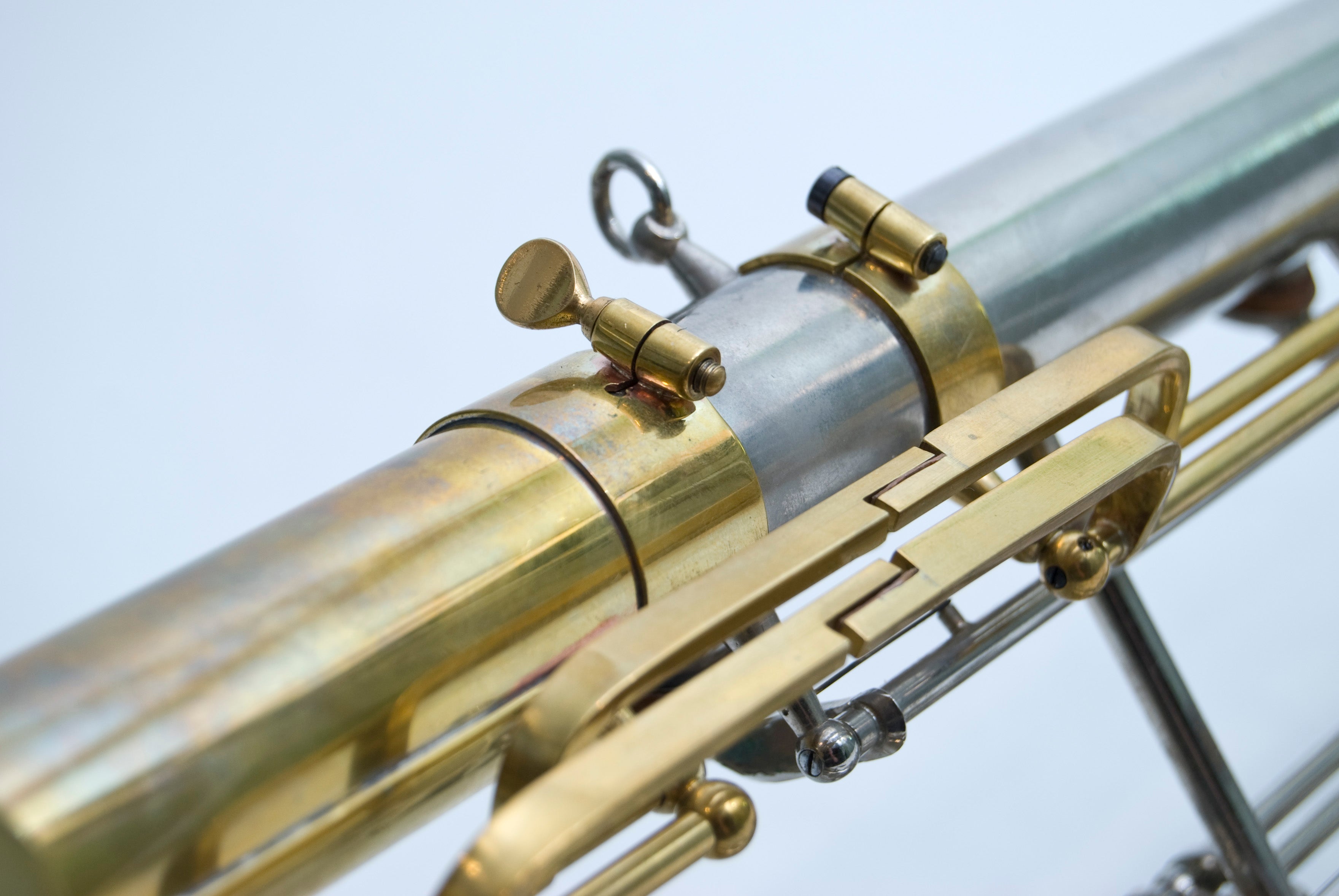
One of the biggest design hurdles was figuring out how to attach the keys to the body without modifying the instrument in any way. On paper, the earliest design iterations saw the extension system attaching the groups of key posts via brass strips that would be soft soldered onto the instrument body. While simple for a tech to install, secure, and not technically permanent, this was not an ideal solution since it would involve the extra cost of having to send the instrument to a local tech for installation after purchase. It also presented another unforeseen problem: if the idea with this system was to be able to ship them out to contra players, then how would I ensure that the posts would be attached in the exact same spot for every instrument? My solution was to mount the posts on a series of half rings which fit around the body tube of the clarinet using a peg/hole to establish a firm connection, and a screw to increase tension and secure a fit. To solve the problem of showing where to install the rings, each ring has a half circle cut into its edge. This is meant to fit snugly around a particular post on the body of the contra, ensuring that each post only has one specific place along the body on which it can fit; trying to put the rings literally anywhere else on the body will result in posts that are obviously out of alignment.
The c clamp before mounting the post, showing the peg/hole system which locks the clamp in place, allowing the screw to tighten on the instrument body.
The completed ring assembly before cleaning up and buffing
In order to account for minor discrepancies in manufacturing from clarinet to clarinet (should there be any) I decided to fit the posts with Conn-styled set screws so that even if the rings are installed in the correct place and the spacing is still slightly off, vertical play can be easily removed by adjusting the depth of the pivot screws. Designing the rings in this way not only creates a surprisingly stable connection to the body of the instrument, but it also provided another benefit in that the extension system can actually be installed or uninstalled by anyone comfortable enough with their abilities, without removing any keys or doing any additional work.
The pivot screws for the extension tube. Unlike the screws for the body keys which emulate those seen on vintage Conns, these could be normal pivot screws since their posts would be set in the same place each time, negating the need to adjust for horizontal motion. Each screw was made out of steel and blackened with heat and oil to add a corrosion resistant finish.
The unfinished ring clamps before cutting in half. The screw posts were brazed on beforehand to make alignment easier, and to get a more even cut.?
Modifications
One of the advantages of designing an instrument from the perspective of a technician that specializes in vintage instruments, is that I have the ability to see how the design of an instrument impacts its condition over time. In that way, I'm in a unique position to be able to pick out weak points in an instrument and modify the design accordingly. In the case of the standard Leblanc low C contras, one issue that I almost universally come across finds itself in the tenon which connects the Low C tube and the lower joint, which is typically ill fitting and too loose. I have no doubt that this joint would have been a tight fit straight out of the factory, but decades of attaching and detaching the Low C tube typically result in a visibly flared joint which can neither make an airtight seal, nor a firm contact. Normal, repeated wear and tear is most likely the main factor in this process, but additionally, the geometry on these tenons is very short and wide which means that it's easier to accidentally assemble the two joints while applying a slight angle. In other words, the ratio between width and height on Low C tube receivers are more narrow than something like a saxophone neck (which, comparatively, is much taller than it is wide) so minor adjustments to horizontal angle will have a larger impact on tenon alignment, and would be easier to accidentally apply at a faulty angle. This, over time, would exacerbate the flare on the tenon, and loosen the contact between the two joints.
In order to fix this, one of the first modifications I made to the original design was to extend the extension receiver, increasing the surface area of the tenon which increases friction. Additionally, a thumb screw was added to enable the receiver to tighten similarly to a saxophone neck receiver, which not only helps minimize the effects of changing geometry over time, but also allows the player to firmly secure the extension tube on the body of the instrument. Along with the thumb screw, I made small notches in the receiver which are meant to correspond to a post and a tone hole on the body of the instrument, which ensures proper alignment similarly to the post rings along the rest of the instrument. Another, more minor modification, was to make the right thumb touch pieces larger and angled toward the center of the thumb rest, making accessing them feel more solid and ergonomic.
Going Forward
When all was said and done and the extension system finally came together, I was surprised at how nice it felt to play, and how solid it sat on the instrument. The system did not take an excessive amount of time to install and when properly adjusted, the keys felt firm and moved freely with a satisfying snap. In addition, they sat firmly within their posts, and had next to no play or lost motion. More importantly, the instrument played as intended with a full, distinct chromatic scale, and was expressive enough to achieve a wide range of volume and timbre. However, as functional as the end result was, it was nonetheless meant as a prototype, and moving forward, there are many things I would elect to do differently. Currently, one of the bigger structural flaws with low C contras is the aforementioned issue of the extension tube being so loose on the instrument. My addition of the longer receiver with the thumb screw dramatically alleviates the problem, but it still leaves open the possibility that the end of the extension tube could be knocked around with enough force. To combat this further, later iterations of the extension tube will be fitted with a brace connecting the top of the extension tube to the top of the instrument body near the register keys. This would create a second, solid contact point with the instrument which would not only protect the extension tube itself, but would also provide a second (albeit indirect) physical bridge between the upper and lower joints of the clarinet – the first being the tenon which directly joins the two body joints, which can currently be twisted out of alignment and cause numerous problems throughout the instrument if sufficient preventative measures are not taken. The next addition would be a series of adjustment screws on the Low C thumb touch piece, and on the key feet. The addition of these screws would make setting up the instrument easier and more streamlined for the user, negating the need to apply any sort of adjustment materials since all adjustments could be made using only a screwdriver, and the materials applied directly to the keys by myself before shipment. This would also make the manufacturing process faster since even though it would require more parts to be made, the parts themselves would have much simpler geometry, and would be easier to manufacture overall.
Selecting the right brass or woodwind instrument is a pivotal moment in any musician’s journey. From the durability required by beginners to the nuanced craftsmanship sought by professionals, the differences between instrument tiers are rooted in a century of design evolution. This guide explores the distinct characteristics of student, step-up, and professional models to help you make an informed investment that supports your specific musical goals and growth.
We are thrilled to welcome the Shires Q38 and Q39 contrabass trombones to the shop, offering players a serious and professional entry into the world of true low brass authority. These models acknowledge the diverse traditions of contrabass playing by offering two distinct tuning systems: the Q38 in European tuning (F/D/BBb/AAb) and the Q39 in American tuning (F/Db/C/AA). With additional options for gold or yellow brass bells, these instruments provide the depth and presence required for the most demanding orchestral and film repertoire.
We are pleased to announce the arrival of the Eastman EBC632, EBC832, EBC834, and EBC836 in the shop. From the nimble versatility of the 632 to the massive, "architectural" foundation of the 836, this lineup provides a thoughtful range of sizes and response profiles for every stage of a player's career. Whether you are a conservatory student preparing for auditions or a professional anchoring a symphonic section, these instruments offer a persuasive look at the future of modern CC tuba design.


Share:
What’s on My Bench? Conn 62H Trombone
What's on My Bench? 76 Trombones! (ok, only 22)